What is a sheet metal process hole?
Sheet metal process holes are for the convenience of subsequent sheet metal bending. When the sheet metal bending line intersects at one point, and there is still sheet metal material on the extension line of the intersection point, it is necessary to add sheet metal bending process holes to avoid bending and pulling the material.
How to determine the size of the hole in the sheet metal bending process?
The size of the sheet metal process hole depends on the position of the process hole. Generally, when the process hole is opened at the intersection of two edges, the process hole is twice the thickness of the plate. The minimum sheet metal thickness cannot be less than 1.5 times. When bending thick plates, the process hole should be appropriately enlarged when considering the bending rounded corners. The process hole made in this way, after bending, especially for thick plates, the material loss at the bending corner is very serious, it is not beautiful and it is not easy to weld. At this time, it is necessary to improve the manufacturing method of the process hole.
How to leave sheet metal process holes for convenient processing and beautiful appearance?
According to the bending edge wrapping situation, consider the thickness of the plate and the avoidance of the bending fillet to determine the sheet metal process hole. See the illustration below for an example.
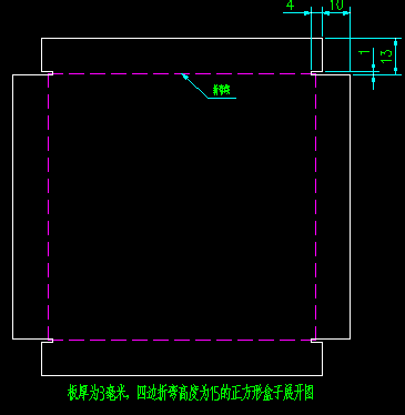
The picture above shows a square sheet metal box with a sheet metal thickness of 3mm and a bending height of 15mm. The picture shows the process hole improvement plan. There are two methods of sheet metal blanking, CNC punching blanking and laser cutting blanking. CNC blanking and bending process holes are generally round holes, and square or long holes are limited by the mold, which is not easy to realize. The picture above shows a 3mm sheet metal part, so laser cutting is used for blanking. The bending process hole adopts a long strip shape, which avoids the aesthetic problem after bending.
How to determine the size of the process hole? I generally set the width of the process groove to 1mm, which neither affects the appearance nor affects the release of sheet metal bending deformation. Depth dimension calculation method: 10 mm = bending height – 3 mm bending coefficient 5; 4 mm = thickness of sheet metal material + 1.
The sheet metal parts bent and formed in this way have only a narrow slit of 1 mm. Look at the three-dimensional renderings:
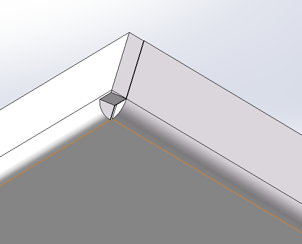
After the process hole made in this way is bent, the bending corner is easy to handle. Basically, it can be welded without solder filling.
The role of sheet metal bending process holes:
(Sheet metal fabrication and laser cutting network) From the above picture, we can see why we need to open process holes. Bending process holes are generally used on sheet metal parts that are wrapped and bent. It is not edge-wrapped and bent. Although it is not necessary to open process holes, the thickness of the material will be reduced in the corners, and fillers are required for welding, which is easy to cause welding deformation. In the case of hemming, the bending process hole can allow the hemming to be smoothly bent in place without bending and pulling the material.
Why avoid bending and pulling materials?
Disadvantages of bending and pulling materials:
- 1. It affects the bending size. During the drawing process, it takes a lot of force to forcibly tear the thickness of the sheet metal. The direction of the force is uncertain, which will cause the workpiece to move, resulting in dimensional displacement.
- 2. The bending mold is easy to be damaged. As mentioned earlier, there will be a lot of force at the sharp corner, which will exceed the bearing capacity of the mold, resulting in chipping and damage.
Standards for use of bending positioning process holes
1. The size and form of the process hole:
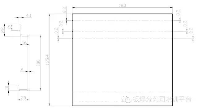
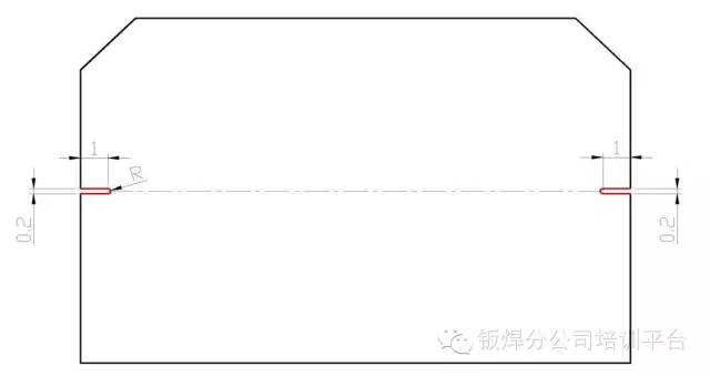
1. Sheet metal bending positioning process hole, the opening size is 1X0.2mm root R 0.1mm, suitable for plate thickness ≤ 3mm.
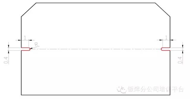
2. Bending and positioning process holes for thick plates, the opening size is 1X0.4mm root R 0.2mm, suitable for plate thickness > 3mm-6mm.
Range of use:
1. Angle type: If the bending angle is not 90 degrees, positioning holes are opened in all bending positions, including edge bending;
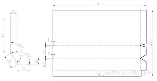
2. Butt joint type: Appearance parts or joint parts with high precision requirements, all positioning holes are opened at the bending position;
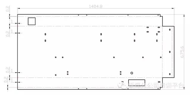
3. Large size type: if the bending size is greater than 200mm, all positioning holes shall be opened at the bending position;
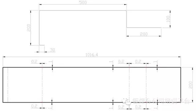
4. Continuous bending complex type: for continuous bending complex parts, add positioning holes from the third bending edge;
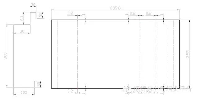
5. Bending sequence type: For parts that cannot be processed according to the normal bending sequence, positioning holes are opened in all bending positions;
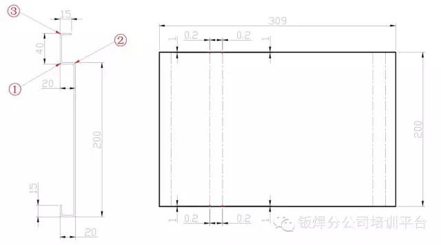
6. Repeated bending type: Due to the limitation of bending equipment, parts that need to be bent repeatedly, all bending positions are opened with positioning holes;

7. Cannot lean against the stop ruler: parts of the stop ruler type cannot be supported, and all positioning holes are opened at the bending position;
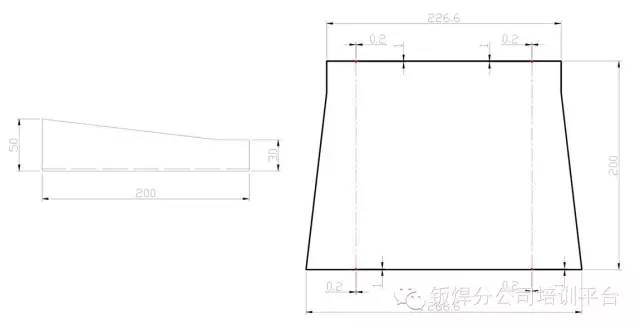
8. Guide rail type: all the bending positions of the guide rail type parts are opened with positioning holes;
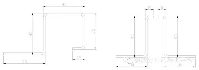
9. Arc positioning hole: the arc starting point at both ends of the arc opens the positioning hole;
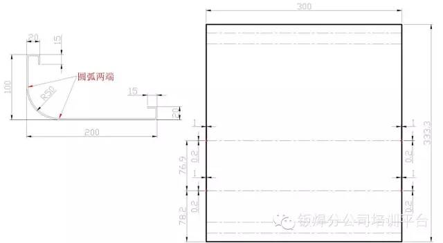
10. Pull plate type: All the bending positions of the pull plate parts are opened with positioning holes.
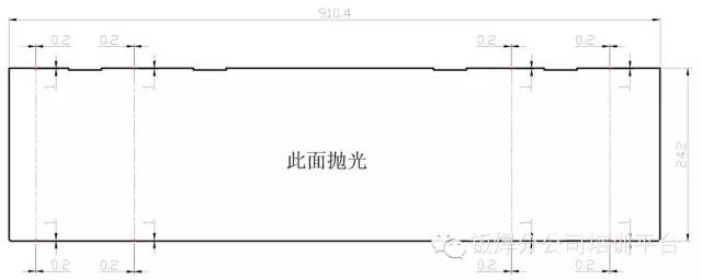
11. Hemming type: positioning holes are opened at the hemming position of hemming parts; positioning holes are opened at the size position of the hemming to continue bending.
